- ISO 9001 Certified
- 60+ Countries
- Made in India
- Warranty Backed
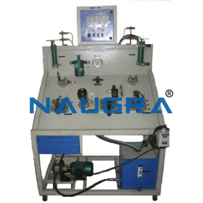
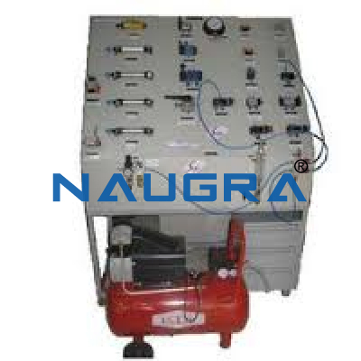
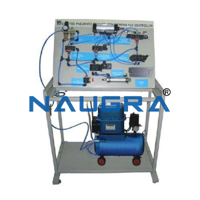
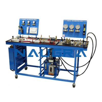
HYDRAULIC LEARNING SYSTEM BENCH
Description & Technical Specification
The most important components at a glance:
1. PRESSURE RELIEF VALVE - HYDRAULIC
The valve limits the pressure at port P relative to the pressure at T to the set value.
Adjustment: manual
Includes non-return valve
Operating pressure 6 MPa (60 bar)
Maximum permissible pressure 12 MPa (120 bar)
Low-leakage, self-sealing coupling nipples
Quantity: 4 (FOUR) units
2. 2-WAY FLOW CONTROL VALVE
The valve ensures a constant volumetric flow rate in the flow direction from A to B, regardless of the load pressure on B. The oil can flow from B to A via the non-return valve which opens.
Actuation: manual
Differential pressure of the pressure balance 0.55 MPa (5.5 bar)
Operating pressure 6 MPa (60 bar)
Maximum permissible pressure 12 MPa (120 bar)
Low-leakage, self-sealing coupling nipples
Quantity: 4(FOUR) units
3. ONE-WAY FLOW CONTROL VALVE
Adjustable by rotary knob
Includes quick connect nipple and socket - nominal size 4 for in-line use
Connectors are self-closing, quick connector type with minimal oil leakage
Operating pressure p: 6 MPa (60 bar)
Maximum pressure pmax: 12 MPa (120 bar)
Opening pressure: 70 kPa (0.7 bar)
Nominal flow rate: 9 l/min
Quantity: 8(EIGHT) units
4. NON-RETURN VALVE, DELOCKABLE
The valve is closed by a locking cone which is pressed against the seat by a spring. The locking cone does not open until X is activated. When the opening pressure on the seat side is exceeded, the valve opens and fluid can flow through it.
Actuation: hydraulic
Operating pressure 6 MPa (60 bar)
Maximum permissible pressure 12 MPa (120 bar)
Low-leakage, self-sealing coupling nipples
Quick action mounting system Quick-Fix®
0.05 MPa (0.5 bar) opening pressure
MPa (6 bar) opening pressure
Quantity: 4(FOUR) units
5. NON-RETURN VALVE
The valve is closed by a locking cone which is pressed against the seat by a spring. When the opening pressure on the seat side is exceeded, the valve opens and fluid can flow through it. When the pressure on the spring side is greater, the valve remains closed.
Actuation: hydraulic
Tube length 1000 mm
Operating pressure 6 MPa (60 bar)
Maximum permissible pressure 12 MPa (120 bar)
Low-leakage, self-sealing quick coupling sockets
Quantity: 4(FOUR) units
6. 4/2-WAY HAND LEVER VALVE, SPRING RETURN
Actuation: manual
Operating pressure 6 MPa (60 bar)
Maximum permissible pressure 12 MPa (120 bar)
Valve port pattern, hydraulic ISO/DIN 4401 size 02
Low-leakage, self-sealing coupling nipples
Quick action mounting system Quick-Fix®
Quantity: 4(FOUR) units
7. 4/3-WAY HAND LEVER VALVE, RELIEVING MID-POSITION (AB > T), DETENTING
Actuation: manual
Operating pressure 6 MPa (60 bar)
Maximum permissible pressure 12 MPa (120 bar)
Valve port pattern, hydraulic ISO/DIN 4401 size 02
Low-leakage, self-sealing coupling nipples
Quick action mounting system Quick-Fix
Quantity: 4(FOUR) units
8. 4/3-WAY HAND LEVER VALVE, CLOSED MID-POSITION, DETENTING
Actuation: manual
Operating pressure 6 MPa (60 bar)
Maximum permissible pressure 12 MPa (120 bar)
Valve port pattern, hydraulic ISO/DIN 4401 size 02
Low-leakage, self-sealing coupling nipples
Quick action mounting system Quick-Fix®
Quantity: 4(FOUR) units
9. SHUT-OFF VALVE
The valve can be closed by turning the lever. This presses a ball onto the seal on the non-pressurized side, sealing off the flow without any leakage.
Actuation: manual
Operating pressure 6 MPa (60 bar)
Maximum permissible pressure 12 MPa (120 bar)
Low-leakage, self-sealing coupling nipples/quick coupling socket
Quantity: 4(FOUR) units
10. DIFFERENTIAL CYLINDER 16/10/200 WITH COVER
Operating pressure 6 MPa (60 bar)
Maximum permissible pressure 12 MPa (120 bar)
Double-acting
Low-leakage, self-sealing coupling nipples
Quick action mounting system Quick-Fix®
Piston Ø: 16 mm
Piston rod Ø: 10 mm
Stroke: 200 mm
Surface area ratio 1 : 1.6
Quantity: 4(FOUR) units
Trusted by Ministries, Institutions & Industrial Buyers
For over four decades, Naugra has manufactured and exported workshop tools, laboratory equipment and turnkey training solutions to engineering colleges, TVET institutions, government tenders and industrial buyers across 60+ countries.
Manufacturer-Direct Pricing
Supplied directly from our manufacturing facility — no intermediaries, competitive export pricing and responsive technical support.
ISO 9001 Quality
ISO 9001:2015 quality management, CE compliance and calibration certificates accompany every shipment for procurement and audit compliance.
Tender & Export Experience
Registered vendor for World Bank, ADB, AfDB, UN and Exim Bank-funded tenders. Full bid-preparation, EMD and performance-guarantee support.
Installation & Training
On-site installation, commissioning, operator training and 12-month warranty cover included for institutional orders.
Interested in HYDRAULIC LEARNING SYSTEM BENCH?
Send us your specifications and quantity — receive a detailed quotation within 24–48 hours.
Request a Quote Call +91-98966-00003Related Training & Tender Products
Related teaching lab products, scientific instruments and educational equipments similar to HYDRAULIC LEARNING SYSTEM BENCH — also available for tender supply and institutional orders.