- Workshop Tools and Workshop Machines India: buy@naugra.com
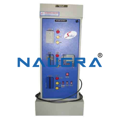
LIFT MODEL .
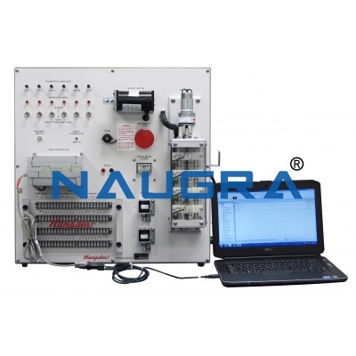
The model must consist of a real three-stop scaled down lift and must allow an innovative approach to PLC control and management. The model must include:
• lift car up-down and position visual signalling at each floor
• photocell on the lift car door to stop its closing in presence of an obstacle
• booking to be effected through buttons with flashing signalling, on priority basis and independently from the lift car position
• lift car geared motor, hoist and electromagnetic brake
• floor, safety and lift car deceleration limit switches
• lift car and floor door open-shut motors
• motor protection thermal relays simulated by buttons
• lift car deceleration, either up and down, near the stop floor
• reproduction of the inside lift car switch panel
• installation graph on the panel
• connection to PLC through terminals or connectors
•28 fault simulators through micro-switches
The panel must be equipped with an internal stabilized power supply unit with the following characteristics:
Output voltage: 24V
Output current: 1A
Thermal protection
Protection against overload
Power supply: single-phase from mains.
A bipolar plug, with relative ground, located on the rear, will allow the system to be supplied at 220 V - 50 Hz.
This trainer must be provided with a fault simulator on the front panel that permit the teacher to perform 8 faults.
All the push buttons, limit switches and motors must be connected to the terminals on the panel, grouped in relation to inputs/outputs and connected to 37-pin connectors on the back side.
All the motors and indication lights shall require a 24 Vdc voltage supplied by the terminals on the panels
Main features:
•Three floors or three stops
• Cabin motor with reducer, winch and electromagnetic brake
• Storey, cabin slowing down and safety limit switches
• Motors for opening/closing the floor and cabin doors
• Motor thermal relays whose operation is simulated through push-buttons
• Photoelectric cell on the cabin ascent/descent and of its location, on the external doors of each floor
• Panel with light indication of cabin ascent/descent and its location, on the external doors of each floor
• Fault simulator, offering the teacher the possibility of entering faults during the simulation through microswitches
• The reservation, displayed by a blinking signal, can be performed at any time, whatever is the cabin location and on the basis of the priority through push-buttons
• Slowing down of the cabin during both the ascent and the descent in the immediate proximity of the stop floor
Faithful reproduction of the push-button panel, normally located inside the cabin, on an external panel; possibility of reservation with signalling through light push-buttons, STOP (ALT) push-button and ALARM push-button.
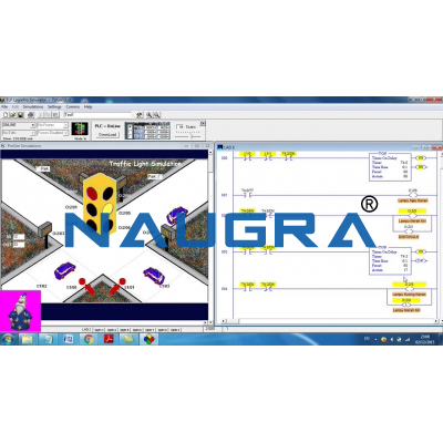
• Graphic representation of the lift with the indication of the marks of the used I/Os
• All the push-buttons, the limit switches, the motors, etc. are connected to the terminals on the panel in front of the metal framework of the lift, grouped according to the inputs and outputs, and to the connectors located on the rear part.
• All the motors and the indicator lamps require a 24 V dc voltage supplied from the power supply terminals, also located on the panel
• To supply each motor a current of approximately 15 mA is enough, because of the presence of an interface circuit.
With this trainer it must be possible to perform the following experiences:
Memorization of performed reservation through floor push-buttons. Light indication of performed reservation through floor push-buttons. Memorization of performed reservation through the cabin push-buttons (push¬button panel)
Light indication of performed reservation through the cabin push-buttons. Memorization of cabin location and direction
Cabin ascent/descent enabled through floor push-buttons
Consents with priority established by sequentiality through floor push-buttons
Cabin ascent/descent enabled through cabin push-buttons
Consents with priority established by sequentiality through cabin push-buttons
Push-button panel priority
Cabin ascent/descent conditions
Cabin ascent
Cabin descent
Electromagnetic brake
Cabin slowing down
Memorization of performed reservation through floor push-buttons for doors opening
Memorization of performed reservation through panel push-buttons for doors opening
Stop at floors and cabin door opening enabled Stop and cabin door opening enabled Cabin door opening Floor door opening. Delayed closing of cabin and floor doors
Instant closing of cabin and floor doors
Cabin door closing
Floor door closing
Thermal protections
Reset of starting conditions
Alarm operation
The model must be connectable to PLC through two connectors (37-pin type) placed on the backside of the panel.Complete with connecting cables, educational manual and control software.
Our Products
Contact Us
6148/6, Guru Nanak Marg, Ambala Cantt, Haryana, India.
For: International Tenders & Enquiry
+91-9896600003 ![]() WhatsApp No.
WhatsApp No.
+91-8199993101 ![]() WhatsApp No.
WhatsApp No.
buy@naugra.com
+91-9896600003

 Login
Login Sign Up