- Workshop Tools and Workshop Machines India: buy@naugra.com
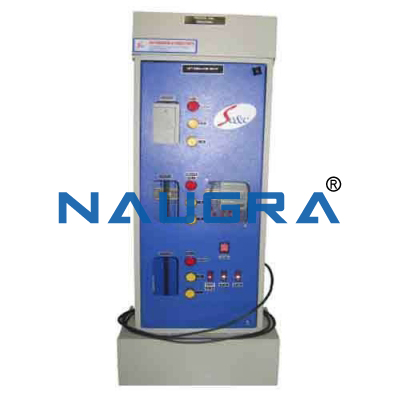
LIFT SIMULATOR .
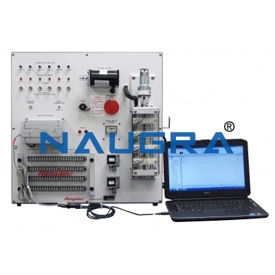
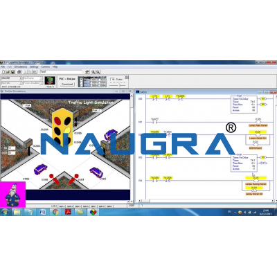
The system must reproduce a three-stop lift with which it shall be possible to simulate realistically all the sequences commonly employed for its use. The control and the automatic management must be carried out by means of PLC. The progressive movement of the cabin through the floors must be displayed through leds controlled by an internal electronic circuit that shall activate the floor limit switches and the safety ones, displayed on the leds too.
The floor reservation, pointed out by a flashing signal, shall happen in any moment independently of the cabin position and in base to the priority. The manual opening and closing of the cabin door and of the side doors must be simulated by means of push-buttons.
A push-button also must simulate the intervention of the protection thermal relay for the motor, while the leds must show the starting of the electromechanic brake of the cabin motor and of the electric lock of the doors of the different floors.Besides the panel must present the faithful reproduction of the push-button panel normally set inside the cabin, with possibility of reservation with indication through bright push-buttons, STOP and ALARM push-button; on the external doors of each floor and on the push-button panel the bright indication of the cabin ascent/descent must be set and of its position as to the different floors.A fault simulator must offer to the teachers the possibility of introducing, through a microswitch, faults during the simulation.
A manual cycle must be also foreseen for the cabin ascent descent, independently of the PLC.
All the LEDs with the exception of the ones displaying the limit switch, must be connected to the terminals of the first left block, that must be connected to the PLC outputs; all the cathodes of the LEDs shall convert to the “com”.
The push-buttons , whose common shall be represented by “com”, on the contrary, must be connected to the terminals of the second right block, that will be on their turn connected through the PLC inputs. The closing of the “reset” push-buttons must reset the initial conditions.
Two 37 pin connectors, set to the rear part, must allow to connect directly the panel to the PLC.
The panel must be provided with an internal stabilized power supply unit with these features:
- Output voltage 24 V
- Output Current 1 A
- Thermal protection
- Overload protection
A bipolar plug, with relative ground, located on the rear, must allow the system to be supplied at 220 V - 50 Hz.
The trainer must be supplied with manual in English language.
Our Products
Contact Us
6148/6, Guru Nanak Marg, Ambala Cantt, Haryana, India.
For: International Tenders & Enquiry
+91-9896600003 ![]() WhatsApp No.
WhatsApp No.
+91-8199993101 ![]() WhatsApp No.
WhatsApp No.
buy@naugra.com
+91-9896600003

 Login
Login Sign Up