- ISO 9001 Certified
- 60+ Countries
- Made in India
- Warranty Backed
PROGRAMMABLE LOGIC CONTROLLER LOGOPROGRAMMABLE LOGIC CONTROLLER LOGO
Description & Technical Specification
It must be a powerful and flexible system that controls a wide variety of devices and meet the different needs of the automation industry.
The LOGO! is a universal logic module that must integrate: • Controls
• Operator and display panel with background lighting
• Power supply
• Interface for expansion modules
• interface for a memory card, battery card, combined memory/battery card,LOGO! PC cable or USB PC cable
• Interface for an optional text display (TD) module
• Pre-configured standard functions, for example, on- and off-delays, pulse relay andsoftkey
• Timers
• Digital and analog flags
After loading the program, the LOGO! unit (CPU) shall contain the logic required for the monitoring and control devices used in the application.
The CPU must monitor the inputs and must change outputs according to the logic of the user program, which can include Boolean logic, counting and timing, complex math functions and for communicating with other devices.
To communicate with the programming device, the CPU must have available an integrated slot. Through it and with a USB PC cable the CPU shall communicate with the PC.
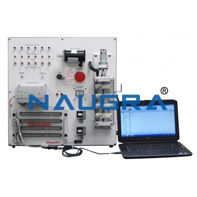
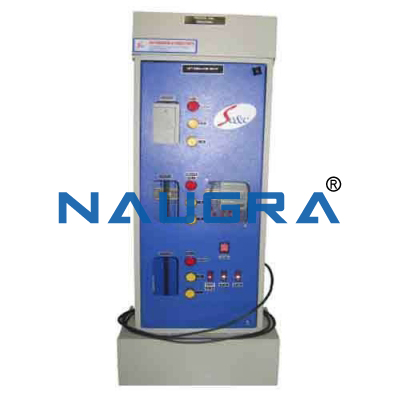
The front panel shall include:
• Output dc voltage: 24V available on two 2mm terminals
• Power supply socket: single-phase from mains
• 12 switches (3 positions: unstable/off/stable) on 1 column for PLC inputs enabling
• Twelve 2mm terminals for inputs
• Twelve 2mm terminals for inputs (common)
• Sixteen 2mm terminals for 8 relay outputs (2 for each)
The module must include:
• Power supply (LOGO!Power 24V/1.3A)
• I/O digital onboard: 8 inputs (24VDC) / 4 outputs (relay, 10A)
• Additional digital I/O (DM8 24R): 4 inputs (24VDC) / 4 outputs (relay, 5A).
• USB PC cable
• LOGO!Soft Comfort (SW)
• Connecting cables
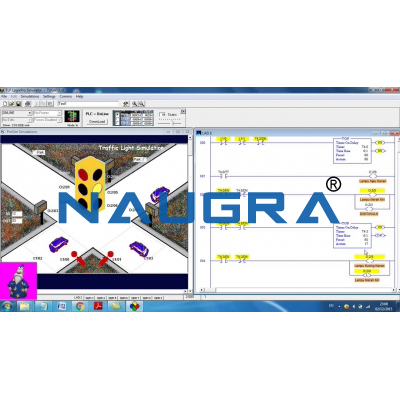
The software must provide standard programming languages that shall allow the development of the control program in a practical and efficient way.
• LAD (ladder diagram) must correspond to a graphical programming language that shall allow to represent the program as electrical circuits.
• FBD (function block diagram) must correspond to a programming language based on the graphic symbols of Boolean algebra
Trusted by Ministries, Institutions & Industrial Buyers
For over four decades, Naugra has manufactured and exported workshop tools, laboratory equipment and turnkey training solutions to engineering colleges, TVET institutions, government tenders and industrial buyers across 60+ countries.
Manufacturer-Direct Pricing
Supplied directly from our manufacturing facility — no intermediaries, competitive export pricing and responsive technical support.
ISO 9001 Quality
ISO 9001:2015 quality management, CE compliance and calibration certificates accompany every shipment for procurement and audit compliance.
Tender & Export Experience
Registered vendor for World Bank, ADB, AfDB, UN and Exim Bank-funded tenders. Full bid-preparation, EMD and performance-guarantee support.
Installation & Training
On-site installation, commissioning, operator training and 12-month warranty cover included for institutional orders.
Interested in PROGRAMMABLE LOGIC CONTROLLER LOGOPROGRAMMABLE LOGIC CONTROLLER LOGO?
Send us your specifications and quantity — receive a detailed quotation within 24–48 hours.
Request a Quote Call +91-98966-00003Related Training & Tender Products
Related teaching lab products, scientific instruments and educational equipments similar to PROGRAMMABLE LOGIC CONTROLLER LOGOPROGRAMMABLE LOGIC CONTROLLER LOGO — also available for tender supply and institutional orders.